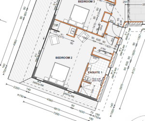
A basic floor plan is a blueprint for the house design. Usually, blueprints are drawn on a 1:100 scale, meaning 1m equals 1cm on the basic house floor plan.
It provides a bird’s-eye view of your house. Dotted lines show the roof and eaves locations, different hatching, squares and lines reference the surface in an area. Each room is labelled, and different symbols indicate what’s inside the room.
Reading Architectural Symbols
To properly understand a professional floor plan, you must know the standard symbols used in blueprints.
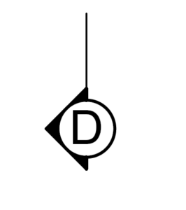
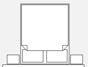
Cross Section
A cross section is simply like slicing the house in two, through a certain reference line as shown on the floor plan. Cross sections are simply labelled A, B, C, or D. It has an arrow showing from which side it’s viewed and a line showing where the vertical plane will cut across the blueprint.
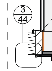
Callouts
Professional floor plans are both complex and consist of many pages. As such, small indicators named callouts show there’s more information on a particular section on another page. A section of the blueprint is circled, and a line connects it to another circle divided in half. The number in the bottom half of the circle shows on which page you can find the relevant information. The number in the top half shows which diagram on that page contains the information.
Dimensions
The dimensions on a basic floor plan will show every aspect of the home design. However, the dimensions are to the framing lines, meaning the timber skeleton of the house. It doesn’t include the GIB (plasterboard) and cladding, so you will need to add 20mm to the dimensions to account for the 10mm plasterboard on each side of the framing.
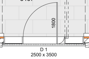
Door and Window Sizes
Whether external or internal, both doors and windows are written in height x width format. Door leaf sizes will indicate which direction the door opens, the type of door used and the size of the door opening. The same also applies for windows.
Other Objects
A blueprint will also show other objects representing the size and where all the furniture and built-in cupboards will go.
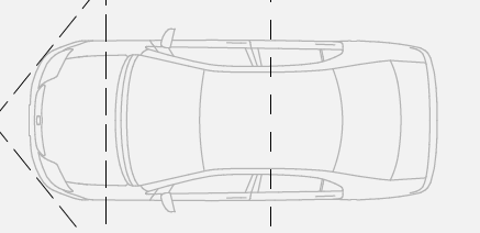
Cars
Cars are very easy to recognize, as a simple outline of a car is shown from the top. It shows the size of the car to the garage or driveway.
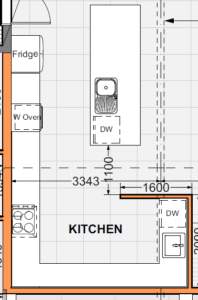
Kitchen
A kitchen will be labelled as such and show lines indicating the counters. Symbols indicate the appliances, such as the oven, fridge, sinks and dishwashers.
Bed
A bed on a basic house floor plan is indicated with a large rectangle with smaller rectangles at the top to indicate the pillow(s).
Bathroom
A bathroom will be labelled as such, with lines and oval shapes indicating things like a bath, showing, sink, vanity, toilet, etc. These items will often be labelled, including the toilet with the letters “WC”, meaning ‘wash closet’.
Reading Architectural Blueprints
A basic floor plan serves as a building blueprint and gives you a visual representation of how it will look once finished. As such, knowing how to read the different symbols on a professional floor plan is essential if you’re starting a new building project.